Why Does LED Blinking Matter? — Understanding Clock and PLL First | AI-Vehicle #4
Why does LED blinking matter in embedded development? Before writing any code, learn how Clock, PLL, and CCU work — and why AI-generated code still needs an engineer to verify it.
AI can now write embedded code. Hand Claude Code a reference manual, and it will figure out the pin numbers, register settings, and timer calculations on its own.
But that raises an important question.
"When AI writes the code, who decides whether it actually works on real hardware?"
That responsibility still belongs to the embedded engineer. When AI sets the CPU clock to 200MHz, you need to know why that value is correct. When PLL registers get configured, you need to verify the math checks out. When a Timer Interrupt fires, you need to confirm the period is accurate.
You can delegate the coding to AI. You cannot delegate the understanding.
That's why, before diving into hands-on coding with the TC275 board, I want to lay down the fundamentals — how the embedded system works, what each peripheral does, and why these concepts matter. Running AI-generated code without understanding it is very different from verifying AI-generated code because you understand it.
Why Is LED Blinking Such a Big Deal?
Anyone who has studied embedded development has probably wondered this at least once.
"Why does every embedded tutorial start with LED blinking? It's just toggling a GPIO pin — what's the point?"
Yes, it's true that using GPIO to turn an LED on and off is about as basic as it gets.
But there's a deeper reason.
The real purpose is to learn how to generate absolute time using interrupts.
Before going further, let me briefly explain what an interrupt is.
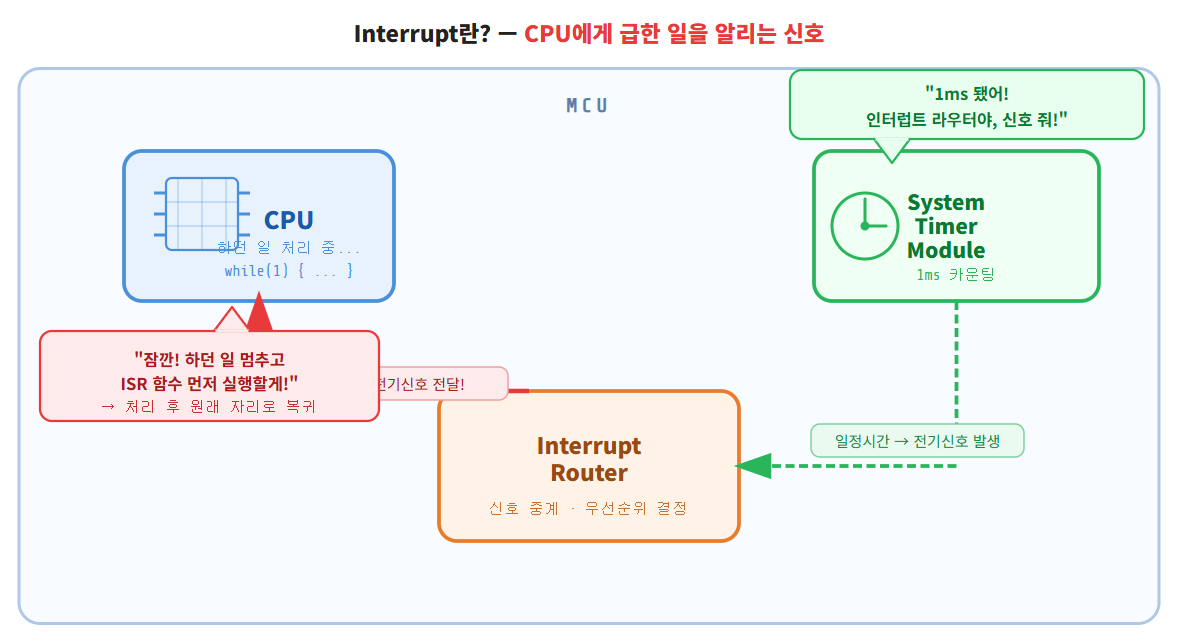
An interrupt is a signal that tells the CPU to pause what it's doing and handle something more urgent first.
For example, when a Timer reaches a set value, it sends a signal to the CPU — "Stop what you're doing for a moment, handle me first." The CPU pauses its current task, executes an interrupt handler function, and then returns exactly where it left off. This mechanism lets you generate precise, consistent time intervals regardless of what else is happening in the code. We'll go deeper on this in the next post.
Embedded SW broadly falls into two categories:
-
Firmware SW — runs without an OS; the developer builds the scheduler directly
-
OS SW — runs on top of an RTOS or embedded Linux
Most small MCUs don't need an OS. In those cases, the developer has to design the scheduler from scratch — and to do that, you first need absolute time.
Even when using an RTOS or embedded Linux, the situation is the same at its core. The OS handles scheduling, but underneath it all, that OS is driven by Timer Interrupts. Whether you use an OS or not, interrupts and absolute time are the foundation of all embedded SW. Understanding this from the start is what separates engineers who can debug from engineers who just run code and hope for the best.
Why You Can't Use a for Loop for Delay
At first glance, this seems like a reasonable approach:
while(1) {
for(i = 0; i < 10000; i++){};
LED_ON();
for(i = 0; i < 10000; i++){};
LED_OFF();
}
Wait a set number of loop iterations, toggle the GPIO, repeat.
Here's the problem.
Say you want to build a digital clock where an LED blinks exactly once per second. What value do you put in that for loop counter?
After a lot of trial and error accounting for CPU speed, you find that 10000000 gives you roughly 1 second. Great.
while(1) {
for(i = 0; i < 10000000; i++){};
LED_ON(); for(i = 0; i < 10000000; i++){};
LED_OFF();
ADD_Function(); // newly added function
}
You add one more function — ADD_Function(). Its execution time adds to the loop. Now 10000000 is no longer accurate. You have to re-tune the value.
Every time you add a function, you tune again. This is not maintainable.
In embedded software, establishing absolute time is one of the most fundamental and critical requirements. LED blinking is where that reality first becomes obvious.
So how do you actually generate absolute time?
You use Timer and Interrupt. And to understand Timer, you first need to understand Clock.
1. What Is a Clock?
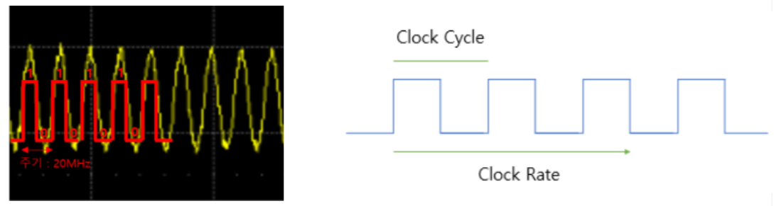
A clock signal is a square wave — it periodically alternates between logical HIGH (1) and logical LOW (0). This signal is used to synchronize the operation of digital circuits.
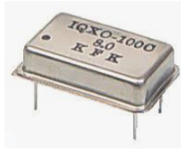
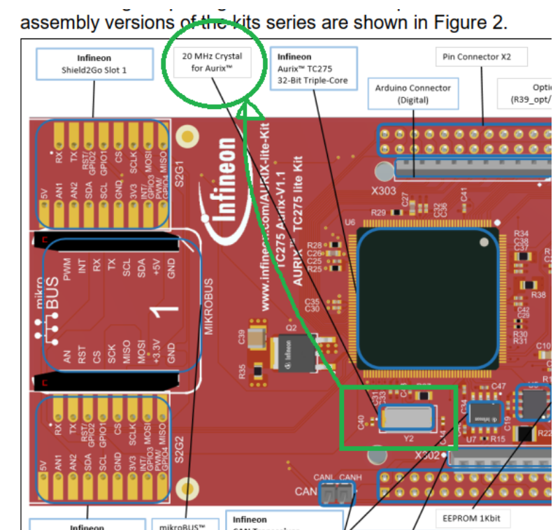
Put simply, the component that generates this signal is called an oscillator. On the TC275 development board, there's a component labeled 20MHz Crystal. It produces 20,000,000 clock pulses per second and feeds them into the MCU.
In the schematic, the oscillator connects to the XTAL1 and XTAL2 pins of the MCU, supplying the clock signal.
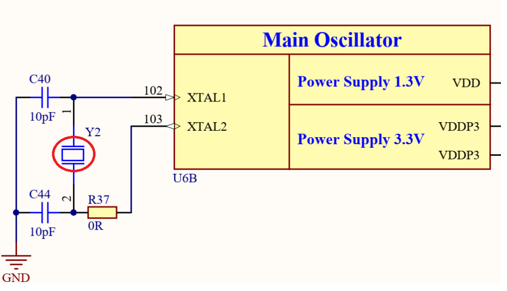
The raw signal from the oscillator is a sine wave, but the MCU digitizes it — anything above a threshold is read as 1, anything below is read as 0. The MCU effectively treats it as a square wave.
So what does the MCU do with the clock?
Two things.
1) The CPU synchronizes its operations to the clock.
Every time the CPU executes code, it goes through three stages:
-
Fetch — retrieve an instruction from memory
-
Decode — interpret what the instruction means
-
Execute — carry out the operation
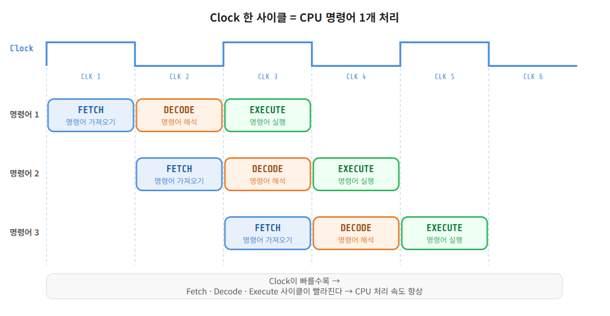
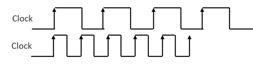
These three stages are synchronized to the clock cycle. The faster the clock, the faster the CPU processes code.
2) The clock is distributed to peripherals so they can operate.
Inside the MCU, there are many peripherals beyond the CPU — Timer, CAN, SPI, I2C, and more. All of them need a clock signal to function.
A Timer module, for example, counts clock pulses. When it reaches a set count, it generates a periodic Interrupt — for instance, every 1ms.
The clock is the heartbeat of the MCU — it drives both the CPU and every peripheral inside it.
2. 20MHz Isn't Enough — Why We Need PLL
The oscillator produces 20MHz. But the TC275 CPU can run at up to 200MHz.
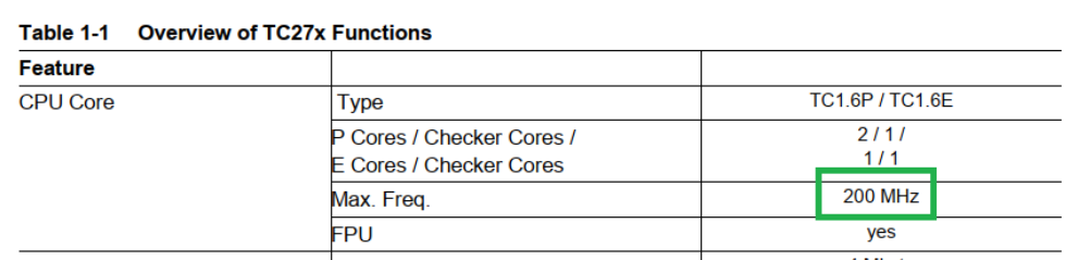
Running at 20MHz means leaving most of the CPU's potential on the table.
So how do you get from 20MHz to 200MHz?
That's what PLL (Phase-Locked Loop) is for.
PLL is essentially a circuit that multiplies a clock frequency to a target value.
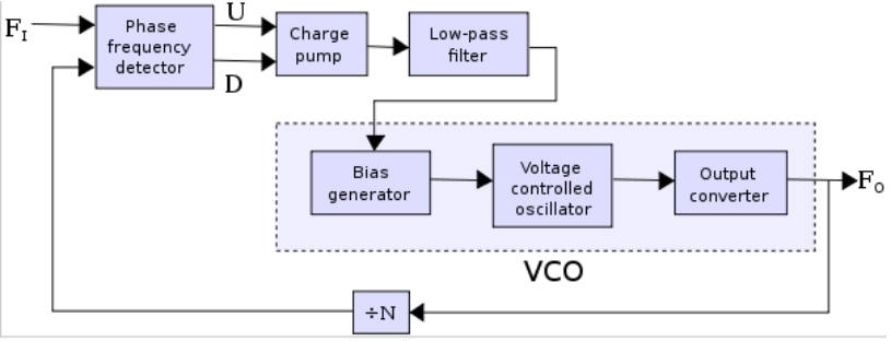
Here's how it works conceptually:
-
FI (Input) — the 20MHz signal from the oscillator
-
FO (Output) — the 200MHz signal we want
-
÷N (Divider) — divides the output and feeds it back for comparison; the loop adjusts until the divided output matches the input
When FO ÷ N equals FI, the feedback loop stabilizes — this is called PLL lock.
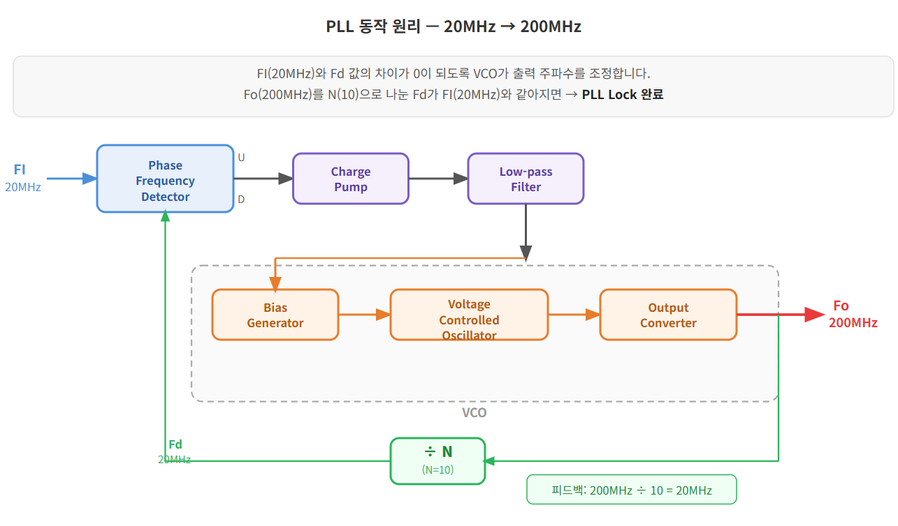
The TC275 PLL formula is:
fPLL = (N / (P × K2)) × fOSC
Plugging in the actual register values:
N = NDIV + 1 = 0x3b + 1 = 60 P = PDIV + 1 = 0x1 + 1 = 2 K2 = K2DIV + 1 = 0x2 + 1 = 3 fPLL = 60 / (2 × 3) × 20MHz = 200MHz ✓
In an ADS project, you configure these values in Ifx_Cfg.h:
#define IFX_CFG_SCU_XTAL_FREQUENCY (20000000) / Input: 20MHz / #define IFX_CFG_SCU_PLL_FREQUENCY (200000000) / Output: 200MHz /
ILLD (Infineon Low Level Driver) reads these settings and automatically initializes the PLL registers inside IfxScuCcu_init(). You don't need to touch the registers manually.
And in practice — this is exactly the kind of setup work we'll hand off to AI.
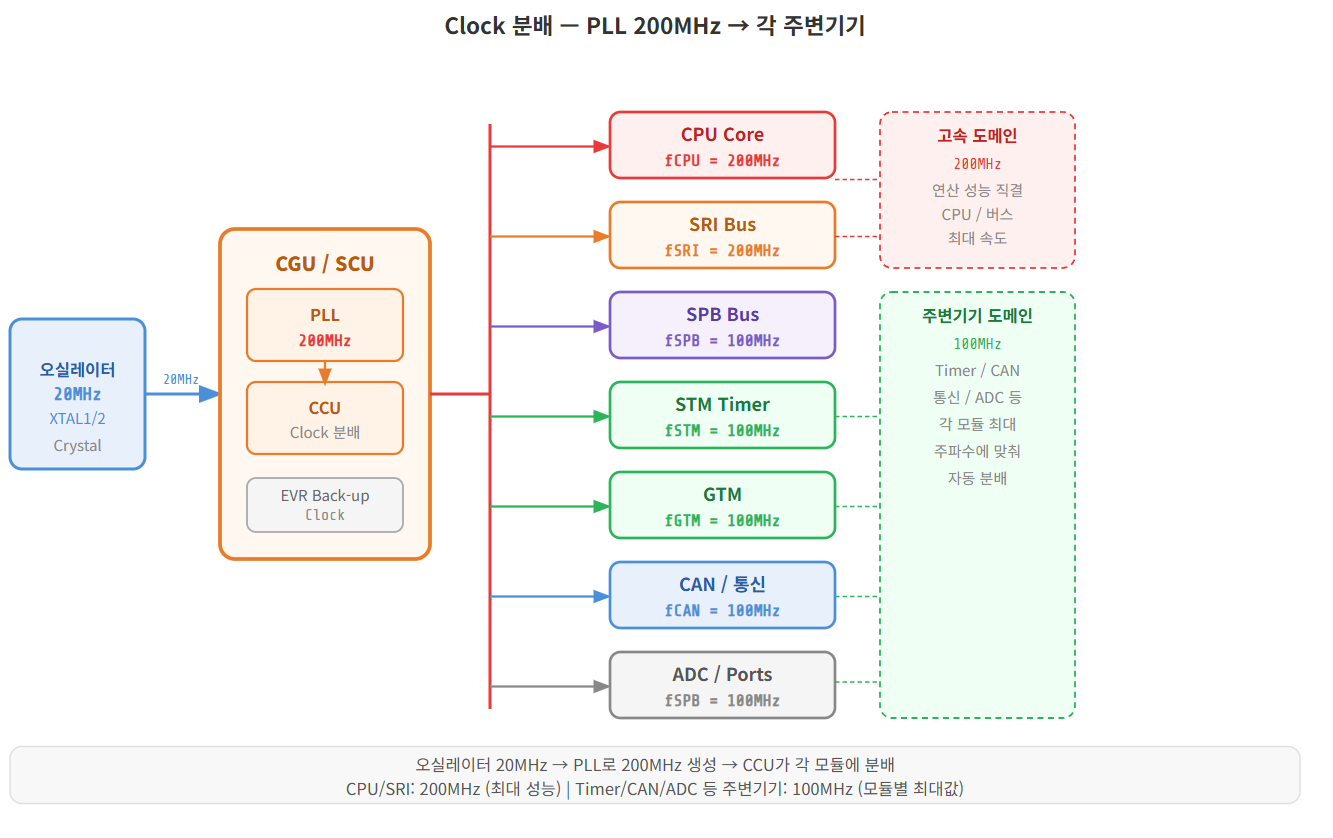
3. Distributing the Clock — Splitting 200MHz Across Modules
Once the PLL generates 200MHz, that clock needs to be distributed to the CPU and each peripheral module.
This is handled by the CCU (Clock Control Unit).
Each module has a maximum clock frequency it can accept, and the CCU automatically configures the distribution to match those limits.
When using the ILLD Driver, this all happens automatically with optimized values:
fCPU0 = 200MHz (CPU core) fSRI = 200MHz (system bus) fSPB = 100MHz (peripheral bus) fSTM = 100MHz (System Timer) fGTM = 100MHz (General Timer) fCAN = 100MHz (CAN communication)
You can verify these values at runtime by inspecting the ClockSettingInfo struct in the debugger — the actual frequencies match exactly what the ILLD driver configured.
Putting It All Together
Here's the one-sentence summary of everything above:
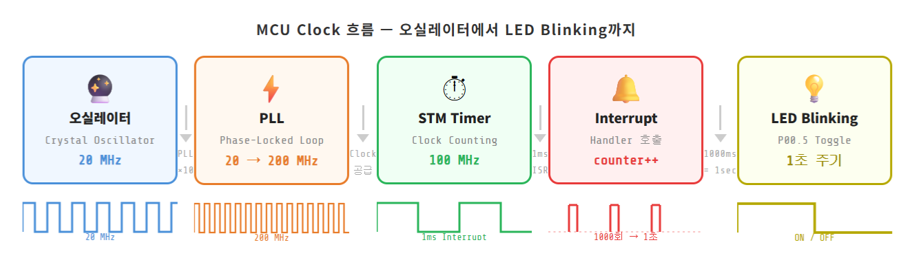
LED blinking is not a GPIO exercise. It's the moment you realize why absolute time matters — and that absolute time requires the full chain: Clock → PLL → Timer → Interrupt.
The complete flow:
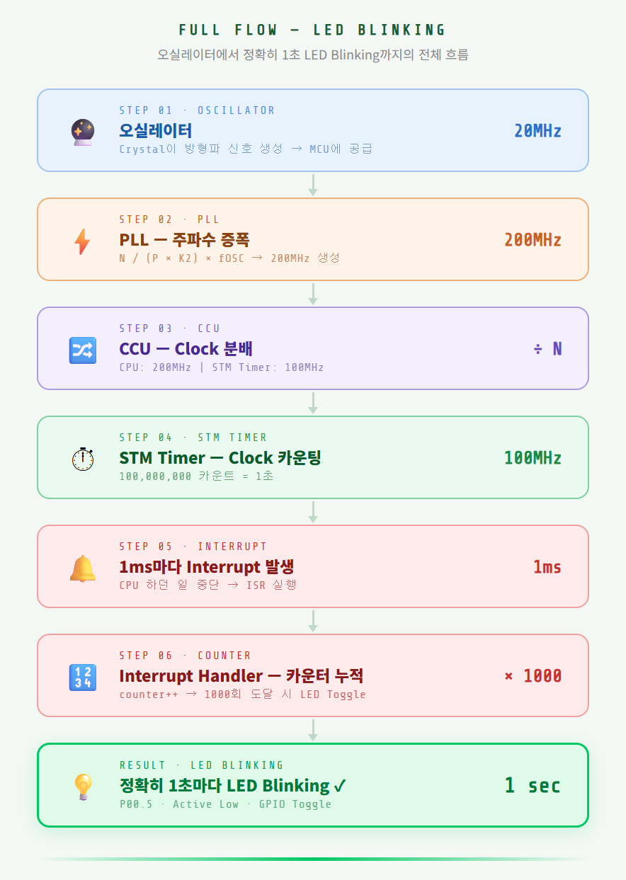
In the next post, we'll dig into the core of this flow — Timer and Interrupt — and walk through how these concepts work inside the TC275.
-
📝 Previous posts in this series
-
EP.01: Embedded Software in the Age of AI — Starting Over From Scratch
-
EP.02: How to Buy the TC275 Lite Board and Set Up Your Dev Environment
-
EP.03: Turning On Your First LED with TC275 — AI Writes the Code
Related Posts
Stay Updated
Get notified when I publish new posts. No spam, unsubscribe anytime.