Turning On Your First LED with TC275 — AI Writes the Code
Learn how to create a project in ADS, build it, download it to the TC275 Lite board, and turn on an LED — with Claude Code writing the embedded C code from the hardware manual.
Hi, I'm AI Craft Toby.
In the last post, I covered how to buy the TC275 Lite board and set up AURIX Development Studio (ADS).
👉 TC275 Lite — How to Buy and Set Up Your Dev Environment
In this post, we finally write some code.
But here's the twist — I'm not writing it myself.
I hand the hardware manual to AI, and let it figure out everything — pin numbers, circuit behavior, timing — on its own. This post shows you exactly how that works.
1. Creating a Project in ADS
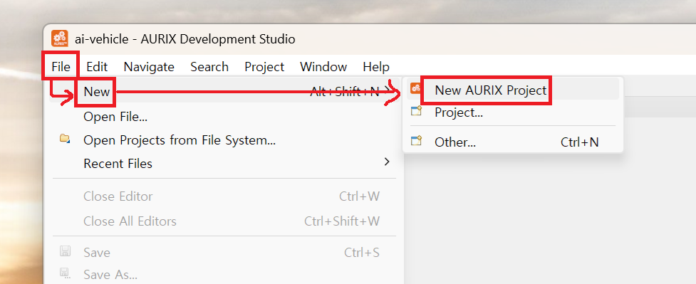
1) File → New → New AURIX Project
Launch ADS and go to File → New → New AURIX Project.
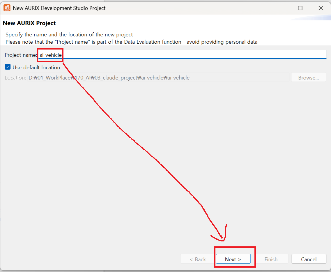
2) Enter a Project Name
Type in a project name and click Next. I named mine ai-vehicle.
3) Select the Board
Choose TC27xTP_D-Step → KIT AURIX TC275 LITE and click Finish.
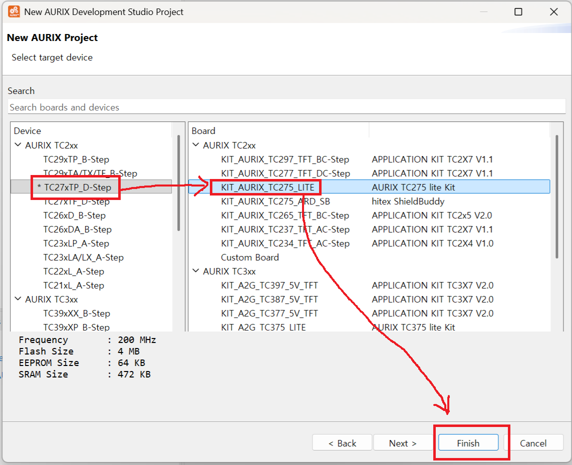
ADS will generate a base project configured for the TC275 Lite board.
2. Building the Project
With the project created, let's run a build.
Think of a build like this: you've written a recipe (C code), and the build process turns that recipe into an actual dish (binary file) the MCU can consume and run.
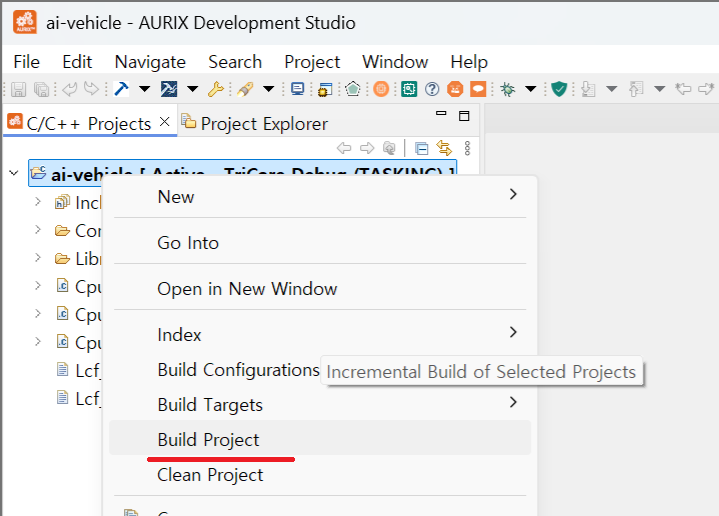
1) Right-click the Project → Build Project
Right-click on the project name and select Build Project.
2) Confirm Build Success and .elf File
You'll see a success message in the console at the bottom. Inside the project folder, a Debug folder appears containing your .elf file.
💡 What is a .elf file? ELF stands for Executable and Linkable Format. It's the binary file that gets downloaded onto the MCU. Once it's on the board, the code runs.
3. Downloading to the TC275 Board
1) Connect the Board via USB
Plug the TC275 Lite board into your PC using USB. The onboard debugger will be recognized automatically — no extra hardware needed.
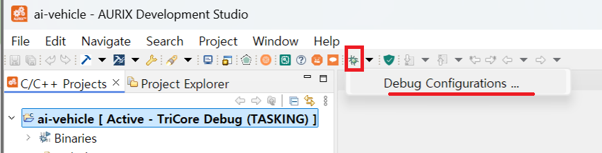
2) Open Debug Configurations
Click the arrow next to the bug icon (🐛) and select Debug Configurations.
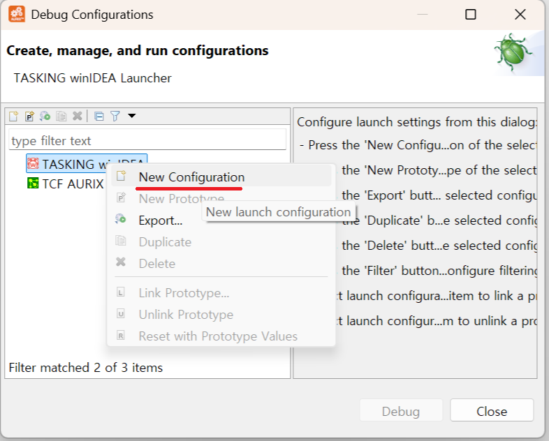
3) Create a New Configuration
Select TASKING winIDEA, right-click, and choose New Configuration.
4) Start Debug
Click Debug. The .elf file will be downloaded to the TC275 board and the debugger will launch.
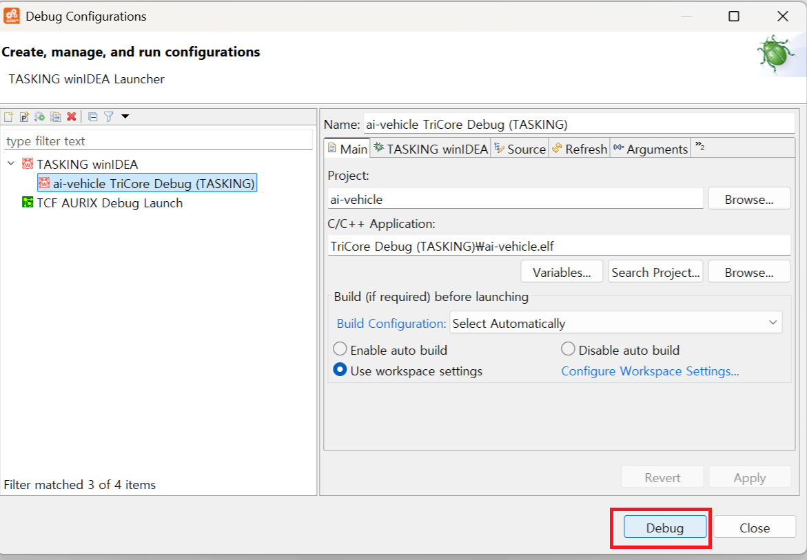
At this point, the code you built is actually running on real hardware.
4. Understanding LED and GPIO — Before We Let AI Write the Code
Before handing things off to AI, you need to understand the circuit. If you don't, you won't be able to tell whether the code AI generates is correct or not.
What is an LED?
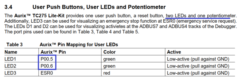
The TC275 Lite board has 2 user-controllable LEDs.
LED stands for Light Emitting Diode — it's a component that emits light when current flows through it. In embedded development, controlling an LED is the very first output exercise. Think of it as the embedded equivalent of "Hello, World!"
What is GPIO?
The pin that controls the LED is called a GPIO — General Purpose Input/Output pin.
It's the MCU's way of communicating with the outside world. It works in two directions:
-
Input mode — reads external signals. For example, when you press a button, voltage enters the pin and the MCU detects it.
-
Output mode — sends signals out. This is what we're doing here. We configure pin
P00.5as output and write0or1to its register to turn the LED on or off.
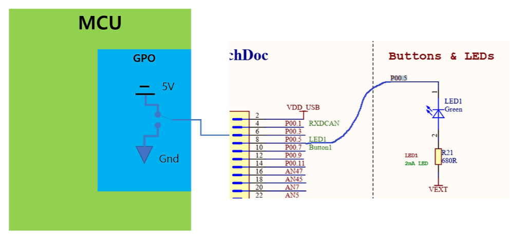
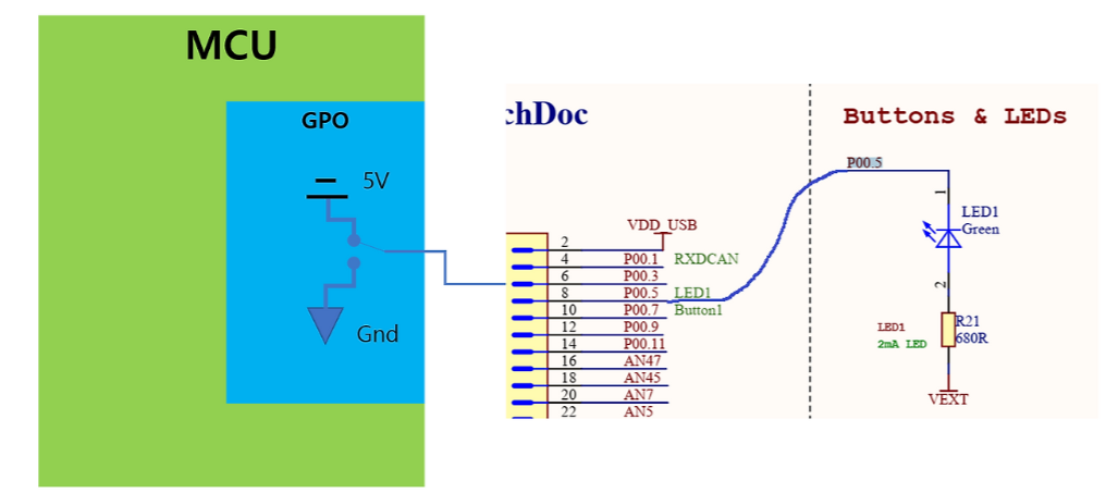
How the LED Circuit Works
LED1 on the TC275 Lite is connected to pin P00.5. The circuit looks like this:
VEXT(5V) ── R21(680Ω) ── LED1 ── P00.5 pin
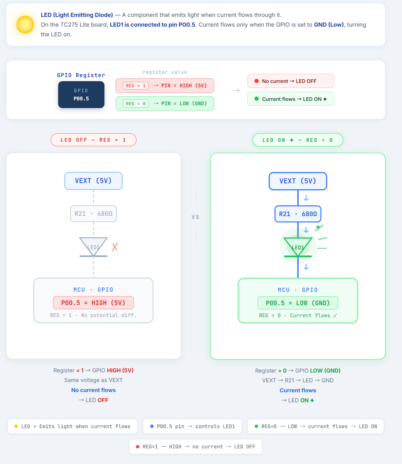
Here's the key:
-
Register = 1 → P00.5 = HIGH (5V) → same voltage as VEXT → no current → LED OFF
-
Register = 0 → P00.5 = LOW (GND) → voltage difference → current flows → LED ON
This design is called Active Low. You pull the GPIO down to GND to turn the LED on.
💡 What is outputPushPull mode? It's one of the GPIO output modes — it actively drives both HIGH and LOW states. The difference between Push-Pull and Open-Drain will be covered in a future post.
5. Letting AI (Claude Code) Write the Code
Now that we understand the circuit, it's time to write code.
Instead of looking up register addresses and typing everything manually, I gave Claude Code the hardware manual and let it design the code on its own.
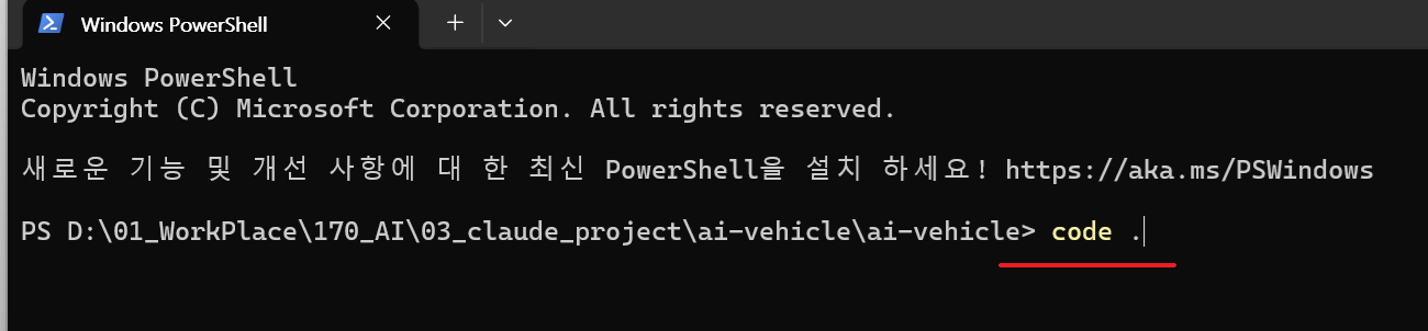
1) Open VS Code
Right-click the project folder and select Open in Terminal.
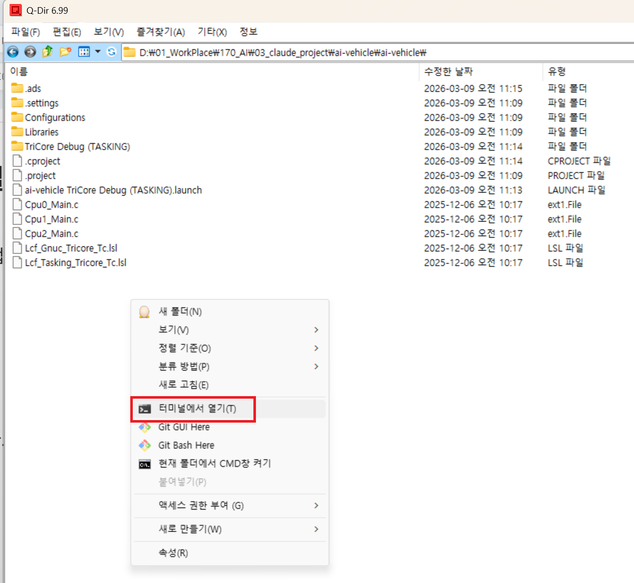
Type code . to launch VS Code in that directory.
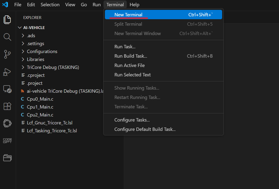
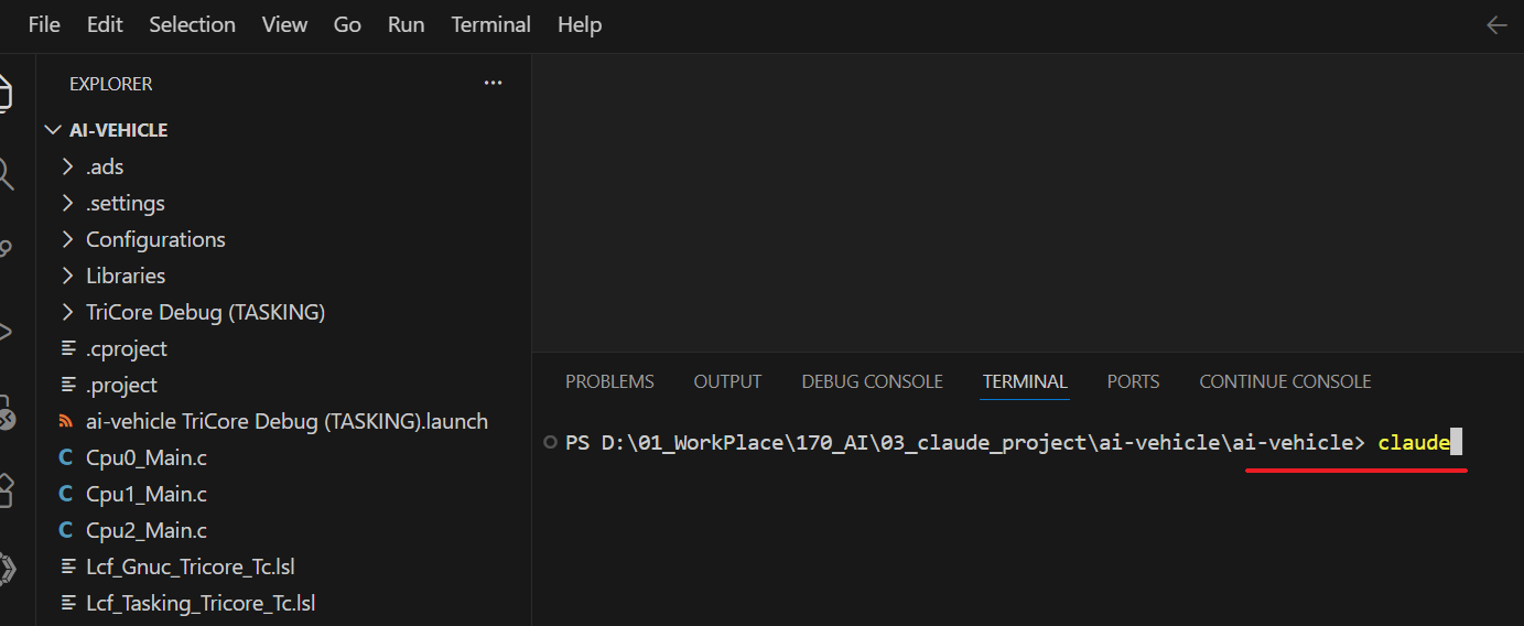
2) Launch Claude Code
In VS Code, go to Terminal → New Terminal and type claude.
If Claude Code isn't installed yet, you'll need to set it up first. Check the official docs or search online for installation instructions.
3) Give Claude the Manual
To give Claude context about the TC275 MCU and board, create a manual folder inside the project and drop in the PDF datasheet and board user manual.
I'll upload these files to Git later. You can also find them through an official search online.
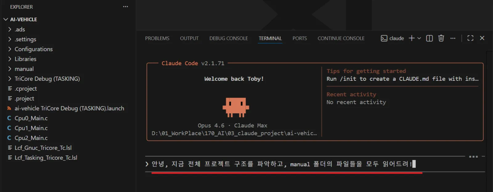
4) Ask Claude to Read the Project
Ask Claude to read through the project structure and all files in the manual folder.
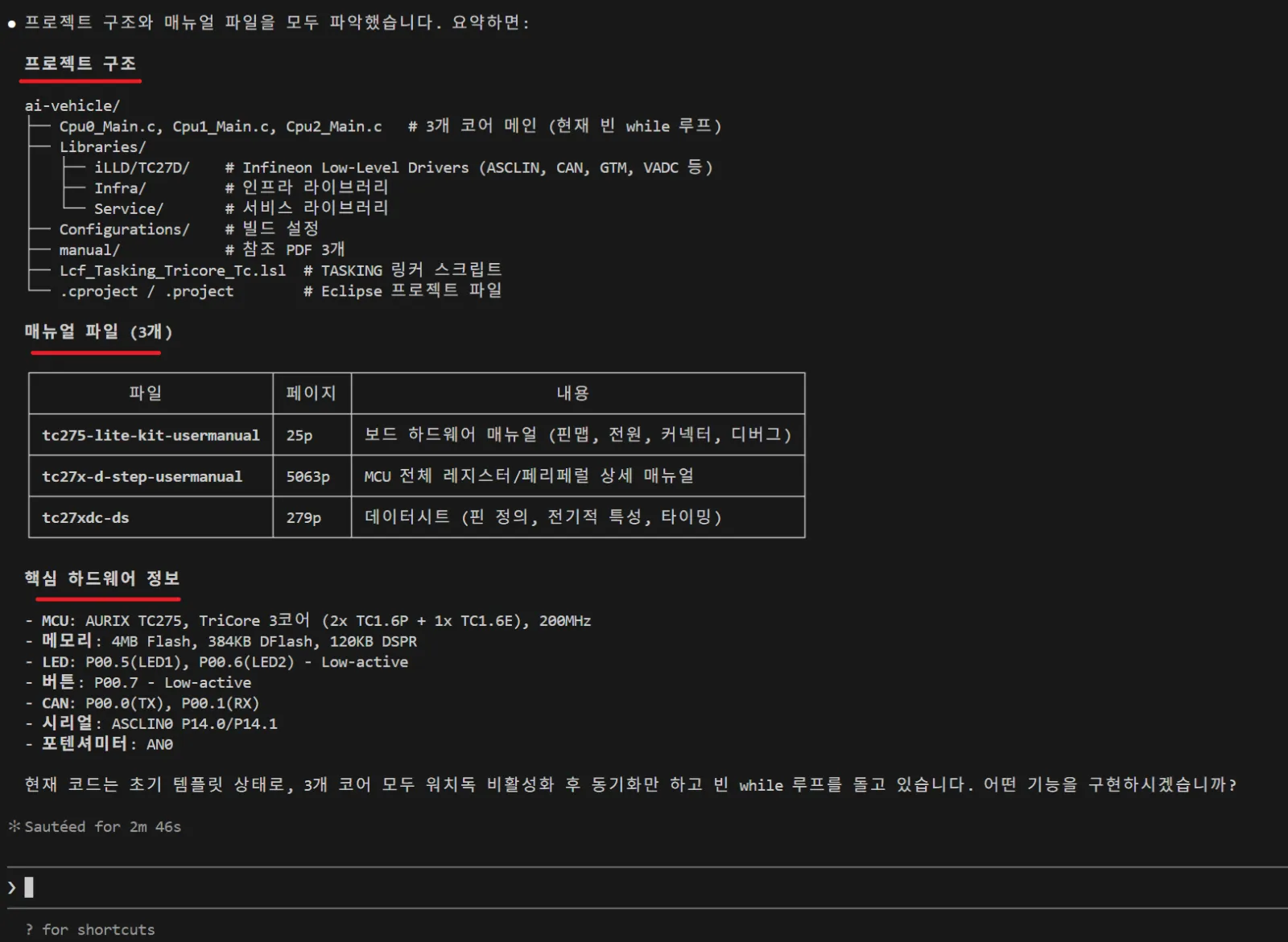
Claude has now processed the project files and manuals.
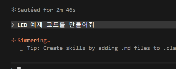
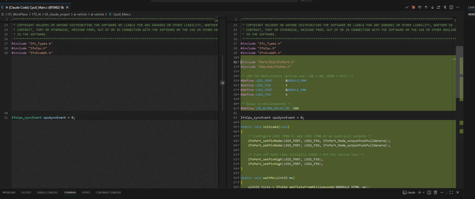
5) Request the LED Control Code
Now ask Claude to design the LED control code.
The code is generated. Click Accept to apply it.
6) Ask Why It Made These Decisions
After receiving the code, I asked Claude to explain its design choices. Here's what it said:
LED Blink Code — Design Rationale
1. Why P00.5 and P00.6?
From the board manual, Table 3: LED1 → P00.5 (green, Low-active) LED2 → P00.6 (green, Low-active)
2. What does Low-active mean?
PIN = HIGH → LED OFF PIN = LOW → LED ON Current flows only when the pin is pulled to GND.
3. Why use the STM timer for delay?
STM (System Timer) is a hardware timer that starts counting automatically at power-on. A simple for-loop delay is unreliable because the compiler may optimize it away. STM guarantees accurate timing.
Claude read the manual, identified the correct pins, understood the circuit behavior, and chose the right timer — all on its own. This is what using AI in embedded development actually looks like. No manual register hunting required.
6. Running and Checking Registers
1) Run the Debugger
After building, click Debug. LED1 should light up on the board.
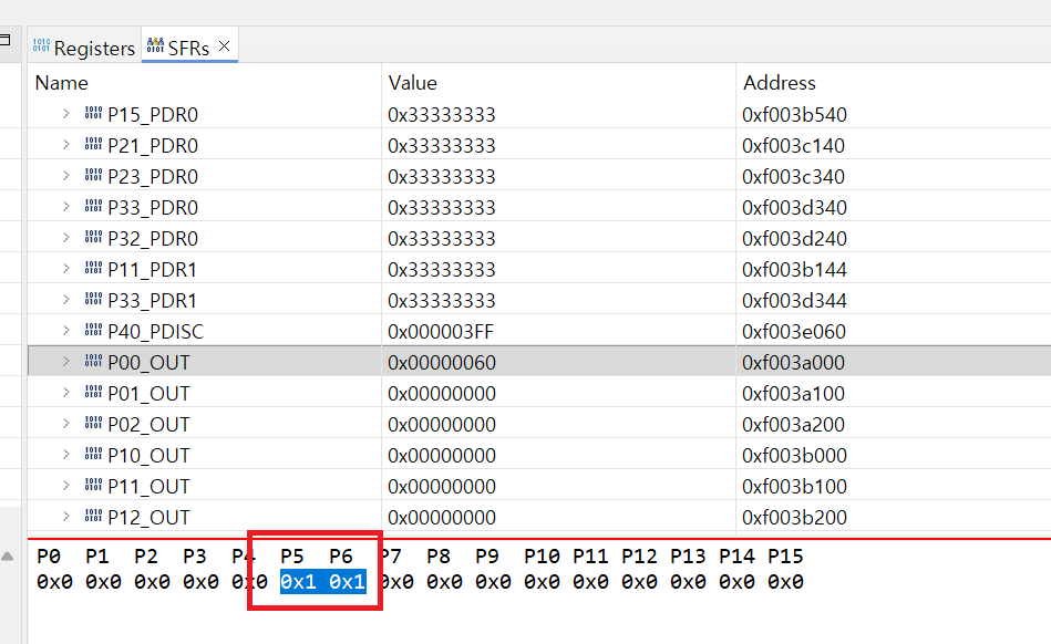
2) Check the SFR Register Value
In the debug view, go to SFRs tab → P00_OUT. You'll see that bit P5 is set to 0.
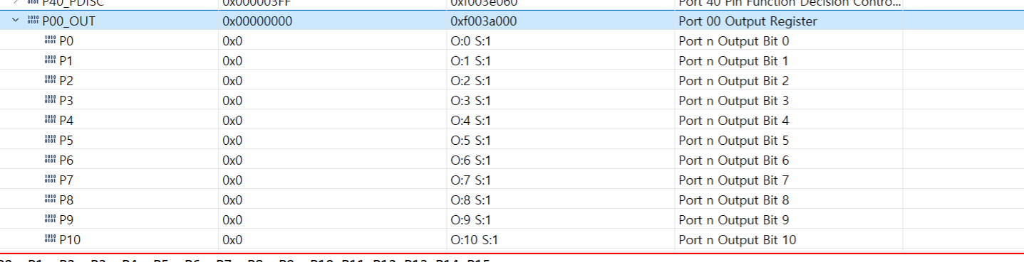
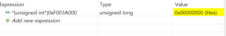
If you manually change that value to 1 in the debugger, LED1 turns off.
7. What's Next — Blinking Every 1 Second
We successfully turned the LED on and off.
If you look at the code Claude generated, it already uses the STM timer for a 500ms delay. In the next post, we'll dig into why that matters — and walk through Clock, PLL, Timer, and Interrupt concepts one by one.
Summary
-
Create a project in ADS, build it, and you get a .elf file ready to download to the TC275 board via USB.
-
The TC275's LEDs are Active Low — write 0 to the GPIO register to turn the LED on.
-
Give Claude Code the hardware manual and it figures out pin numbers, circuit behavior, and timing logic on its own.
-
Push-Pull vs. Open-Drain will be covered in the next post.
Embedded development moves faster with AI than you'd expect.
— AI Craft Toby | aicraftlog.com
Related Posts
Stay Updated
Get notified when I publish new posts. No spam, unsubscribe anytime.