Timer and Interrupt — How to Create a Heartbeat in Embedded SW
Learn why for-loop delays break timing in embedded systems, and how Timer + Interrupt creates a rock-solid 1ms Time Base on the TC275 MCU. Part of the AI-Vehicle series.
AI-Vehicle EP.05 | Concept Edition
Introduction
In the last episode, I said this:
LED Blinking is not just a simple GPIO exercise. The real goal is Time Base — building an accurate time reference.
And to build that Time Base, the chain of Clock → PLL → Timer → Interrupt must all fall into place.
In this episode, I'll break down the core of that chain: what Timer and Interrupt are, and why they matter.
The actual code comes next episode, written together with Claude Code. This one is all about getting the concept right first.
1. Why Can't We Just Use a for-loop Delay for an Accurate 1ms Period?
When you first start embedded development, you'll probably see code like this:
// pseudocode
while(true) {
    delay_loop(10000000);   // kill time
    LED_ON();
    delay_loop(10000000);   // kill time
    LED_OFF();
}The idea is to spin a loop a fixed number of times to "waste" enough time.
What's the problem?
The moment you add more code, the timing falls apart.
// pseudocode
while(true) {
    delay_loop(10000000);
    LED_ON();
    delay_loop(10000000);
    LED_OFF();
    do_something();    // the loop now takes longer by exactly this function's runtime
}Adding a single do_something() changes the total loop execution time. Now you have to re-tune that 10000000 value. Every time you add a function, repeat.
This is an unmaintainable structure.
In embedded SW, when you do something matters just as much as what you do. Motor control, CAN communication, sensor sampling — all of it requires precise timing. That timing cannot depend on how long your code takes to run.
That's exactly why we need Timer and Interrupt.
2. Polling vs Interrupt — Two Ways a CPU Talks to Peripherals
Before diving into Timer and Interrupt, let's nail down one of the most fundamental concepts in embedded systems.
There are two ways a CPU communicates with peripherals.
Let's use a concrete example: an airbag impact sensor that outputs LOW normally, and goes HIGH when a collision is detected.
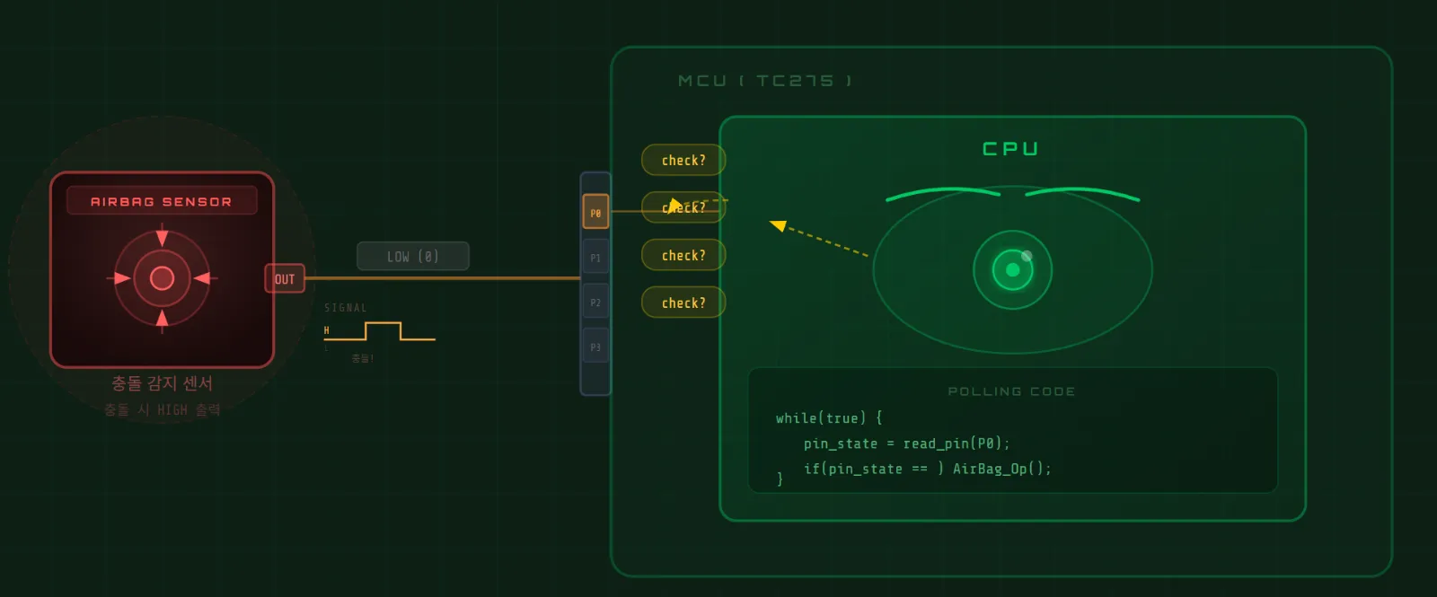
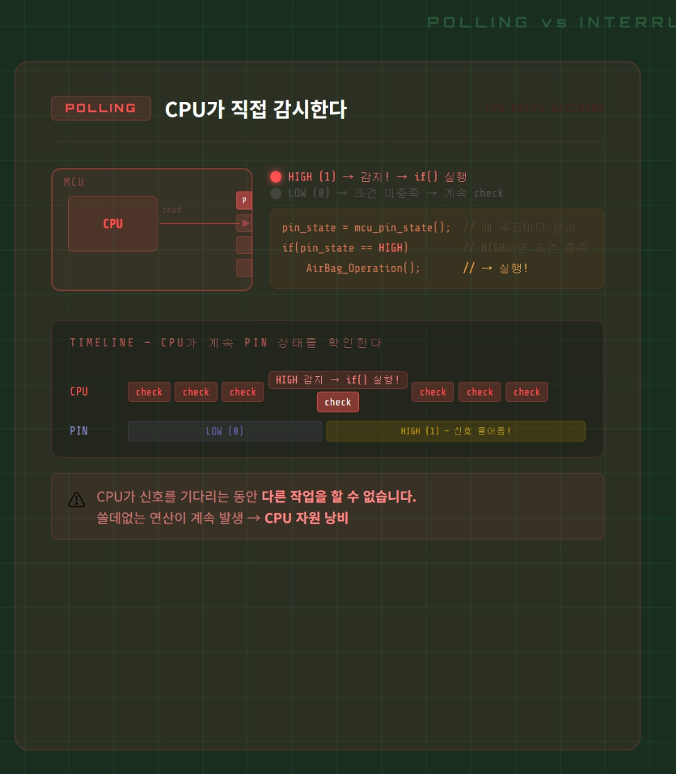
Polling — The CPU Watches Directly
// pseudocode
while(true) {
    state = read_pin();      // CPU keeps checking
    if(state == HIGH) {
        do_action();
    }
}The CPU continuously reads the pin state to check whether something happened.
Imagine monitoring an airbag sensor this way. The CPU must constantly check the pin — and while it's doing that, it can't do anything else.
Pointless computation running nonstop.
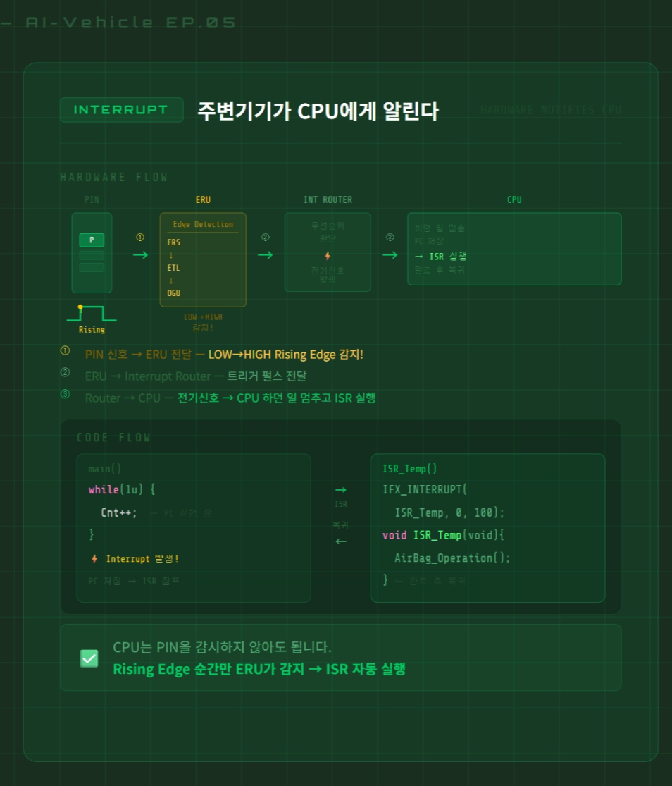
Interrupt — The Peripheral Notifies the CPU
// pseudocode

// Main loop — CPU does its own work
while(true) {
    do_main_task();
}

// ISR — runs automatically when the signal arrives
void ISR_Handler(void) {
    do_action();             // handle it
    return_to_main();        // go back
}When a peripheral has something to report, it sends an electrical signal to the CPU. The CPU pauses what it was doing, runs the agreed-upon function (the ISR), then returns exactly where it left off.
No watching. No waiting. React only when needed.
| Polling | Interrupt | |
|---|---|---|
| CPU load | High (constant checking) | Low (only when needed) |
| Response time | Depends on check interval | Immediate |
| Code structure | Simple | ISR requires separate design |
| Typical use | Simple state monitoring | Timers, communication, sensor events |
3. How an Interrupt Actually Executes
When an interrupt fires, what actually happens inside the CPU?
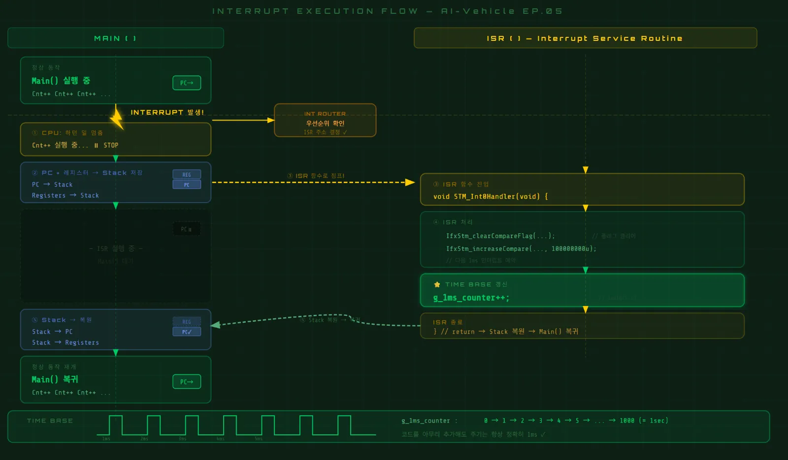
Two things are critical:
① The CPU doesn't forget what it was doing Before pausing, it saves its current state (PC, registers) onto the Stack. So when the ISR finishes, it can return to the exact instruction where it stopped.
② The Interrupt Router acts as a traffic controller Multiple peripherals can request interrupts simultaneously inside an MCU. The Interrupt Router evaluates priority and forwards the most urgent one to the CPU first.
4. Timer — The Module That Counts Clock Pulses
With Interrupt understood, let's look at Timer.
A Timer is a module that counts incoming clock signals.
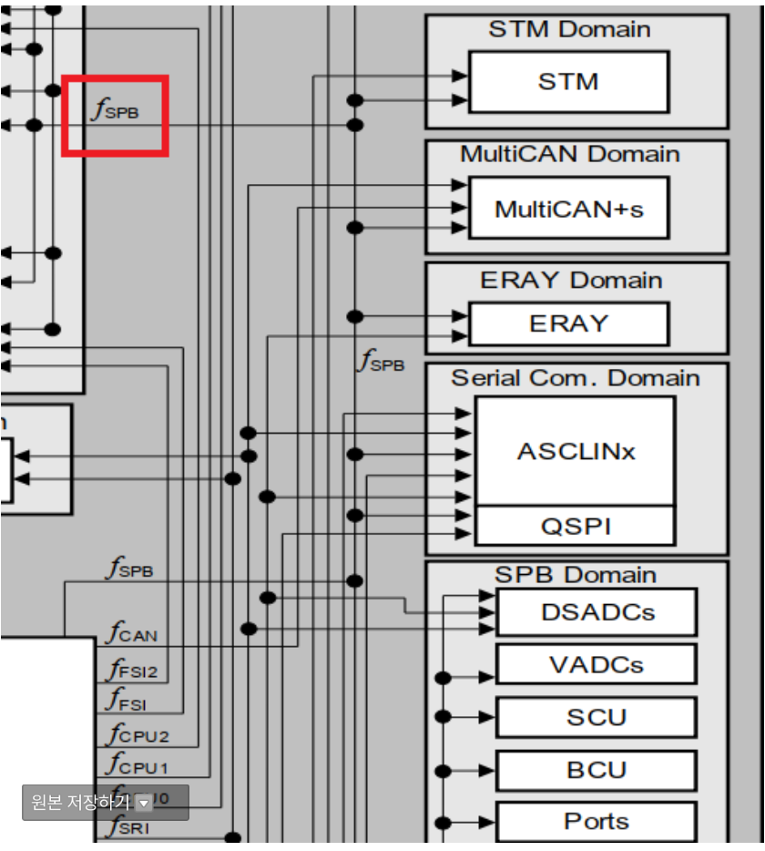
Take the TC275's STM (System Timer Module) as an example:
fSTM = 100MHz
→ 100,000,000 counts per second
→ 100,000 counts per 0.001s (1ms)
This is where the CMP (Compare) register comes in.
// pseudocode
CMP = 100,000; // set the target
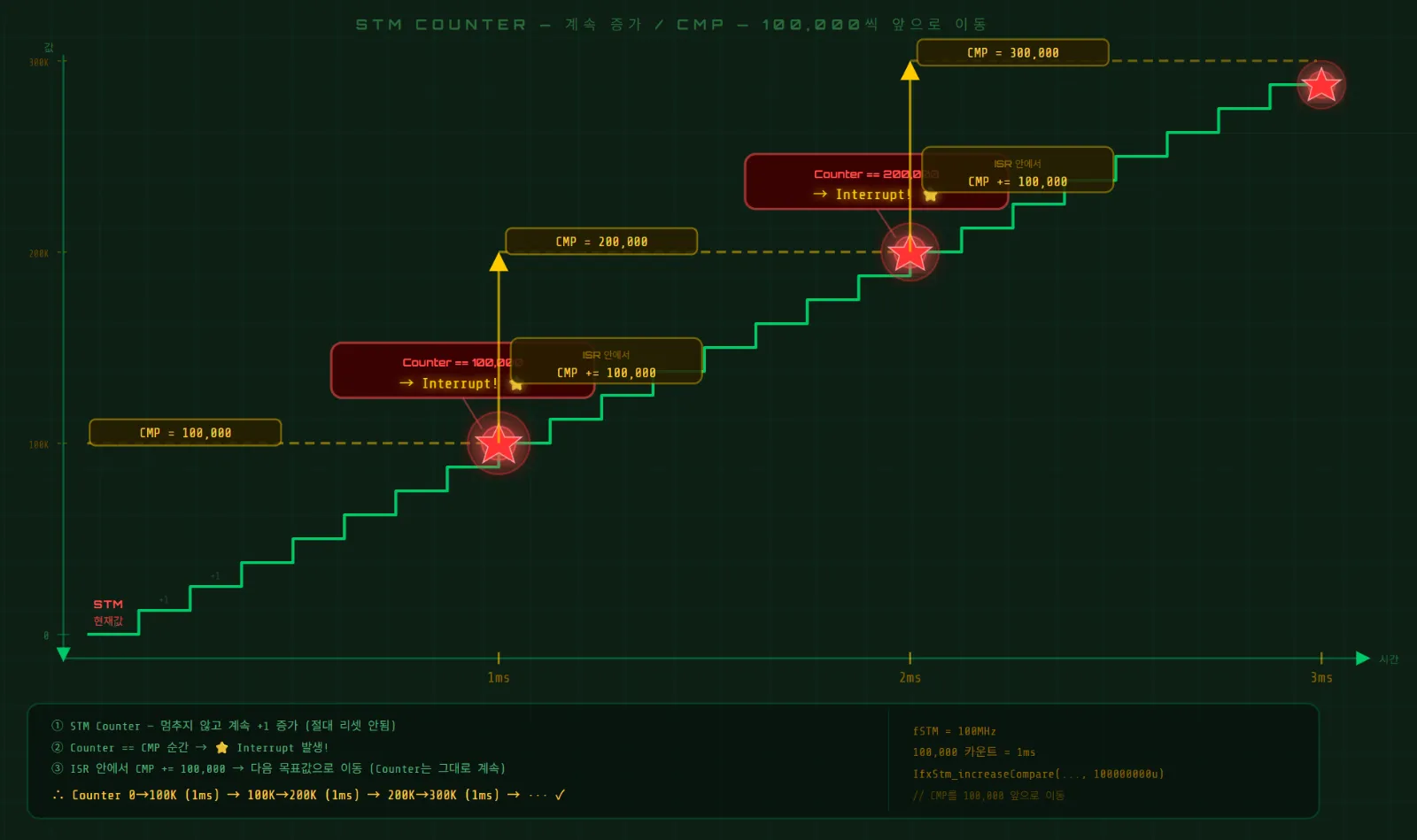
STM Counter keeps climbing...
when Counter == CMP
→ Interrupt fires!
→ ISR runs
→ CMP += 100,000 (schedule the next interrupt)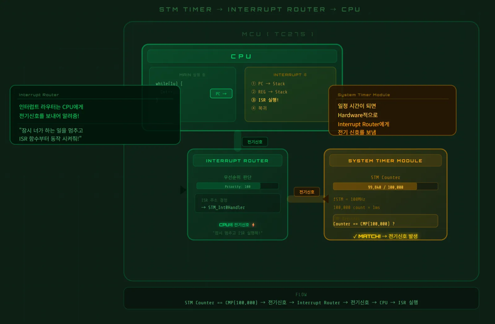
The instant the STM Counter matches the value in CMP, an interrupt is generated.
The full sequence:
Clock 100MHz
    ↓
STM Counter — +1 every clock
    ↓
Counter == CMP (100,000)?
    ↓ YES
Interrupt fires
    ↓
ISR runs → CMP += 100,000 (schedule next 1ms)
    ↓
ISR repeats every 1ms ✓
5. Time Base — The System's Clock Reference
If the ISR executes every 1ms, we can increment a counter variable inside it:
// pseudocode
unsigned long g_1ms_counter = 0;

void STM_ISR(void) {
    g_1ms_counter++;           // +1 every 1ms
    // schedule next interrupt
}That g_1ms_counter variable is the Time Base.
Read it at any point and you know exactly how many milliseconds have elapsed since the system started.
// pseudocode — scheduler example
void Scheduler(void) {
    if(g_1ms_counter % 1   == 0) Task_1ms();    // every 1ms
    if(g_1ms_counter % 10  == 0) Task_10ms();   // every 10ms
    if(g_1ms_counter % 100 == 0) Task_100ms();  // every 100ms
}Here's the fundamental difference from a for-loop delay:
This period is completely independent of code execution time.
Add 100 functions inside Task_1ms() — g_1ms_counter still increments exactly every 1ms. Because Timer and Interrupt operate at the hardware level.
This is why Time Base matters so much in embedded SW.
6. The Full Picture
Everything covered in this episode, in one flow:
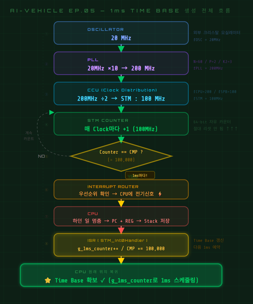
Once this structure is in place, blinking an LED every second looks like this:
c
// pseudocode
void STM_ISR(void) {
    g_1ms_counter++;

    if(g_1ms_counter % 1000 == 0) {   // 1000ms = 1 second
        LED_TOGGLE();
    }
}Compare that to the for-loop version. Add as much code as you want — the LED still blinks exactly once per second.
Wrapping Up
Here's what we covered today:
Polling — the CPU keeps watching. Inefficient. Interrupt — the peripheral notifies the CPU. Efficient. Timer — counts clock pulses to generate interrupts at a fixed period. Time Base — the system's time reference, built from those interrupts.
And all of it starts with Clock and PLL.
Next episode, we implement this on the TC275 board. I'll ask Claude Code to write the STM Timer initialization and ISR, then confirm with the debugger that interrupts are actually firing every 1ms.
AI-Vehicle Series — Building an Obstacle-Avoidance Car with the TC275 Board An embedded AI development journey with Claude Code
Related Posts
Stay Updated
Get notified when I publish new posts. No spam, unsubscribe anytime.